Building believable LED walls in Unity
How LED Studio renders LED walls in Unity: a logical emitter grid, shader-side emitters, physical pitch, defects as hardware state, grouped panels and shared clocks.
What I learned while developing LED Studio. If you want to see it in action, visit the LED Studio page.
LED walls look simple from a distance. In a game scene, a stage preview, a stadium environment, or a virtual production setup, it is tempting to treat them as exactly that: an emissive texture on a quad.
That works until the camera moves.
At a distance, the wall should read as a bright continuous image. At medium range, cabinet structure and panel seams start to matter. Up close, the display stops being a flat surface and becomes thousands of individual emitters, each with shape, spacing, falloff, brightness response, and tiny imperfections. If the simulation does not account for that transition, the illusion breaks quickly.
LED Studio grew out of that problem. The goal was not just to place videos on surfaces, but to build a Unity tool that treats an LED wall as display hardware: logical pixels, physical pitch, emitter reconstruction, cabinet structure, defects, sync, and multi-panel composition.
Here is the trailer: LED Studio trailer on YouTube
This post is a look at the technical setup behind the tool and the design decisions that made it hold together.
The Core Model: A Logical Board First
The most important architectural decision was to separate content composition from LED presentation.
Instead of asking the scene mesh to be the display, LED Studio creates a logical board. A board might be 40 x 40 emitters for a chunky sign, 192 x 108 for a small 16:9 wall, or much larger for venue-scale displays. Sources are composed into a board-resolution RenderTexture first. Only after that does the shader present the board as visible LED hardware.
That split keeps the system understandable:
- C# manages board state, render textures, source discovery, playlists, layout layers, sync clocks, dirty regions, and runtime API calls.
- The shader manages emitter reconstruction, diode shape, brightness response, cabinet seams, close-up detail, distance blending, and defect application.
This avoids the common trap of building one overloaded material shader that knows too much about everything. It also avoids the opposite trap: placing thousands of meshes or GameObjects into the scene to represent individual emitters.
The board is a data model first. The visual surface is just one way to present that model.
Shader-Side Emitters Instead Of Geometry
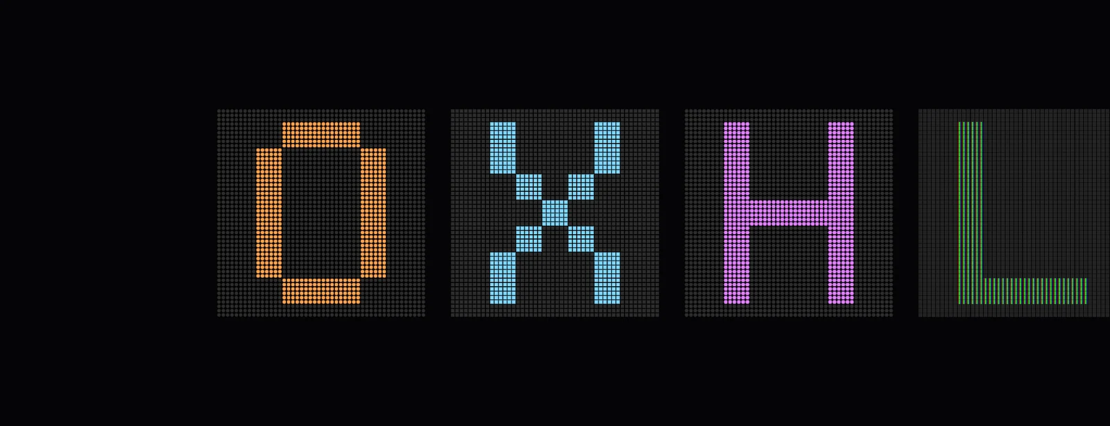 Four boards show the letters O, X, H and L with round, square and hexagonal emitters and, on the L board cut off at the right edge, red, green and blue LCD subpixel stripes.
Rendering every LED as geometry sounds attractive for about five minutes. Then the numbers get uncomfortable.
A modest 192 x 108 wall already contains 20,736 emitters. A larger video wall can go far beyond that. If each emitter becomes a mesh, a transform, or an individually managed object, the scene pays for that decision constantly. Authoring becomes heavier, batching gets more fragile, and every layout or resolution change becomes a geometry problem.
LED Studio keeps the scene geometry simple and reconstructs emitters procedurally in the shader.
The shader receives the logical board texture and the board resolution. From the interpolated UV, it calculates which emitter cell the pixel belongs to, the local coordinate inside that cell, and the shape mask for the selected emitter type. Circle, rounded square, and hex-style emitters become variations of the same reconstruction process.
This gives the renderer a few useful properties:
- The board mesh can stay simple.
- Resolution changes do not require rebuilding emitter geometry.
- Emitter shape can be changed per board.
- Close-up diode detail can be controlled by shader parameters.
- The same content path works for flat, curved, ribbon, and grouped boards.
The important part was not just drawing a dot pattern. Static dot patterns shimmer badly once the camera moves. LED Studio uses distance-aware behavior: close up, the shader reveals diode structure, dark gaps, and subtle lens response; farther away, the board blends toward a smoother image to reduce harsh aliasing and moire.
That transition is where the effect starts to feel like display hardware rather than a decorative screen-door overlay.
Physical Pitch Gives The Renderer A Scale
LED walls are usually described by pitch: P2.5, P3.9, P5, P10, P20, and so on. Pitch is the spacing between emitters in millimeters.
Adding pitch to the board model changed a lot. It means the tool can derive physical size from logical resolution. A 192 x 108 board at P3.9 is not just “192 by 108 pixels”; it represents a different physical object than a 192 x 108 board at P10.
That matters for:
- automatic board sizing
- minimum viewing distance
- close-up shading thresholds
- cabinet proportions
- believable scene scale
Without pitch, most controls become artistic sliders. With pitch, the board has a relationship to real-world display hardware.
The user can still push values for creative reasons, but the defaults come from a concrete model.
Content Sources Are Adapters Into The Board
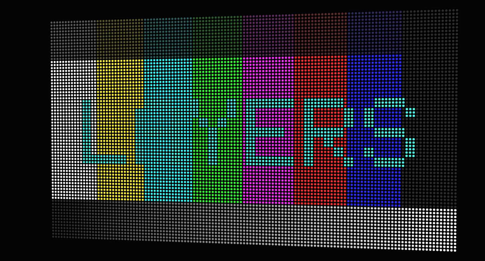 One board composes several layers: vertical color bars, teal LAYERS lettering across them, a dimmed color band along the top and a gray-to-white gradient along the bottom.
Once the board became the center of the system, sources became easier to design.
A source does not need to know about cabinet seams, emitter shape, or shader presentation. It only needs to provide content for the logical board. Text, images, video, render textures, uGUI, UI Toolkit, timers, scoreboards, and integrations all become adapters into the same composition pipeline.
Each source has a stable ID. Layout layers can bind to those IDs, and runtime code can update them without needing direct references to every component. That enables workflows like:
- set the text of a scoreboard slot
- replace an ad texture
- feed a camera render texture into a board
- schedule multiple layouts in a playlist
- layer a timer over a video
The useful abstraction is small:
- Is the source ready?
- Is it dirty?
- What texture does it output?
- What dirty rects changed?
- How should it update: every frame, on change, fixed rate, or manually?
That last point matters for performance. A scrolling ticker and a live video may need frequent updates. A static logo does not. Treating every source as an every-frame dependency wastes work, especially when several boards are active in the editor.
Defects Are Hardware State, Not Source Content
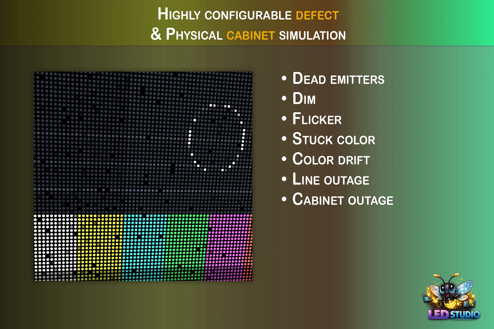 Store image listing dead emitters, dim, flicker, stuck color, color drift, line outage and cabinet outage, next to a board whose color bars show scattered dark and dimmed emitters.
One of the cleaner separations in LED Studio is that defects are not baked into the source texture.
The content path stays clean. A video frame, text render, UI canvas, or chart output is still just content. The board then applies a separate defect mask while presenting that content as LED hardware.
That defect path can represent:
- dead emitters
- dim emitters
- flicker
- stuck color
- color drift
- line failure
- cabinet outage
This makes defects reusable and deterministic. The same source can be shown on a new board, a lightly worn board, or a damaged board simply by changing the defect profile and seed. It also makes temporal defects easier to reason about, because flicker is driven by board time and shader state rather than by rewriting source textures.
The distinction is subtle but important:
Content says what the wall is trying to show.
Defects say how the physical wall fails to show it perfectly.
That separation also keeps runtime control cleaner. Defect severity can be blended, disabled, or replaced independently from playlists and source updates.
Cabinet Seams Belong In Emitter Units
Cabinet simulation introduced a surprisingly easy bug to make.
If seam width is defined in arbitrary UV units, the result depends too much on board aspect ratio and resolution. A seam setting that looks correct on one display can become too heavy, too thin, or misaligned on another.
The fix was to calculate cabinet layout in emitter units. The board knows its logical resolution. The cabinet grid knows its rows and columns. From that, the shader can determine how many emitters belong to each cabinet and place seams relative to the emitter grid.
That keeps cabinet boundaries stable across board sizes.
It also means a user can reason about cabinet structure in the same space as the display itself: emitters, pitch, rows, columns, and physical panels.
Multi-Panel Displays Compose Once, Then Slice
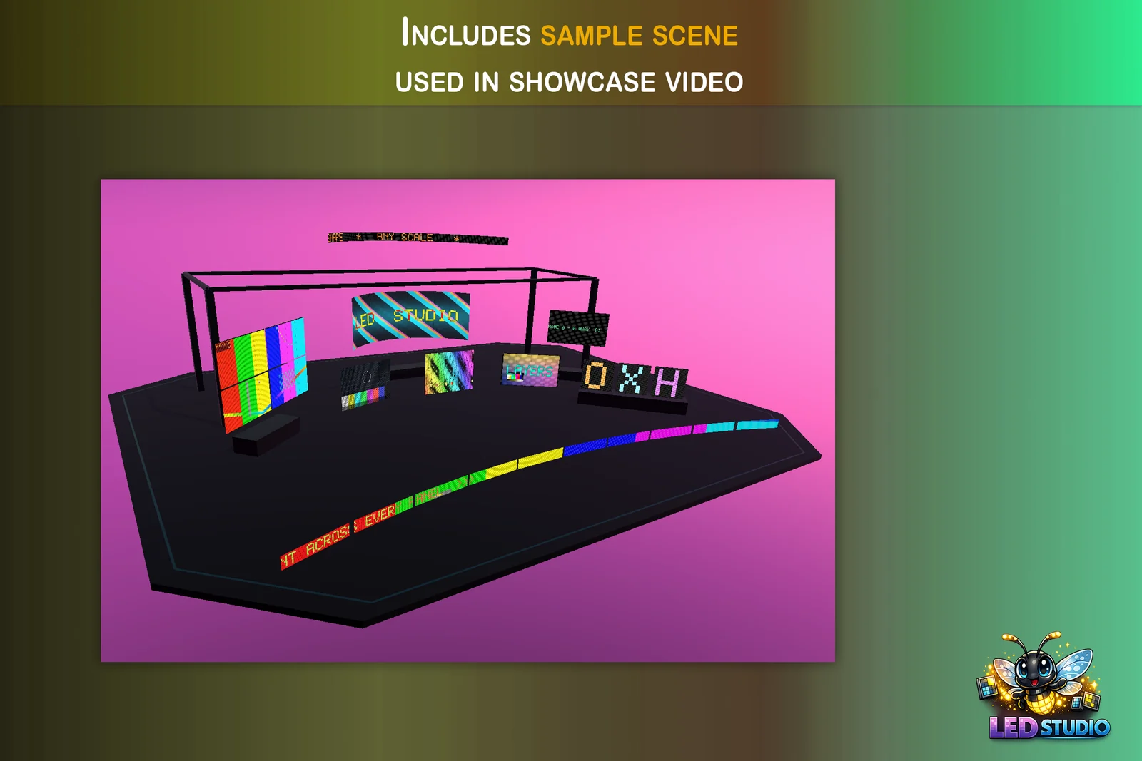 Store image of the sample scene from the showcase video: a 2 x 2 video wall with color bars, a curved board reading LED STUDIO, smaller boards with letters and layers, an overhead ribbon and a segmented ribbon along the stage edge.
Video walls and ribbon boards create a different problem: the display is physically split into panels, but the content often needs to be continuous.
The naive approach is to let every panel compose its own content. That works for simple mirrored boards, but it breaks down for seamless layouts. Timing can drift. Text can repeat. Video can align incorrectly. Bezel gaps become an afterthought.
LED Studio uses a group supervisor for multi-panel setups:
- Discover the child board controllers.
- Calculate the combined master resolution.
- Add optional gap pixels for physical bezels.
- Compose the group layout once into a master
RenderTexture. - Slice the master texture into per-panel render textures.
- Inject each slice into the corresponding child board.
The child boards still own their material instances, shader settings, defects, physical scale, and emitter presentation. The group owns the shared content canvas.
That split is useful because real LED walls often behave exactly like this: one content feed mapped across many physical cabinets, with each cabinet still having its own physical imperfections.
It also keeps layout authoring sane. A designer can think about one wide ribbon display instead of manually distributing fragments across several child objects.
Sync Is A Clock Problem
Once playlists, animated sources, flicker defects, and grouped boards are involved, sync becomes visible.
If each board advances from its own local time, small differences can show up as phase drift. For a single sign, that may not matter. For a set of ribbon boards or a multi-panel venue display, it does.
LED Studio uses shared sync groups. Boards registered to the same group read from a shared monotonic clock. Playlists, animated effects, and timed states can then stay phase-locked across separate board objects.
The useful lesson here was to keep sync boring. A shared clock is much easier to test and reason about than trying to synchronize every source or playlist action individually.
Cross-Pipeline Shader Support Needs Discipline
Supporting Built-in, URP, and HDRP from the same package is not just a matter of duplicating shader passes.
The approach that held up best was to keep the core LED math in shared HLSL includes, then keep the pipeline-specific passes as thin as possible. The shared layer handles things like:
- emitter reconstruction
- brightness response
- seam masks
What LED Studio added since June 2026
This article describes LED Studio at its first release in June 2026. The logical board at its core has stayed the same, while the changelog has added much more around it:
- Content (1.1.0 and 1.2.0): layered compositions, many more playlist transitions and a text engine with TTF fonts and multilingual text, then text scrolling and blinking plus board, group and source timing controls.
- Shapes (1.2.0 and 1.5.0): reusable topology settings for flat, curved, corner and full 360-degree cylindrical boards, later joined by vertical bends for pipe wraps and LED spheres with latitude limits, inside or outside faces and optional closed poles. The curved and spherical screens use case shows them in practice.
- Housing (1.2.0 and 1.4.0): Rear Body adds physical cabinet depth with side and back materials, and generated front frames come in Chamfer, Round, Cove, Ogee, Stepped and custom profiles.
- Hexagons (1.5.0 and 1.6.0): hexagonal boards and cabinet layouts with a honeycomb wall preset, and Cut Out, which removes incomplete hexagonal panels and shapes the rear housing and front frame to the honeycomb edge.
- Spatial groups (1.5.0 and 1.6.0): one canvas mapped across each board’s physical position and size, gaps included. Panels can move, rotate and scale while their content stays attached, and Row, Column, Grid and Honeycomb arrangements place panels with a shared gap. See video walls and panel groups.
- Realtime GI (1.5.0): live-texture emission for compatible global illumination setups, with an example room, so a board can light its surroundings.
- UI Toolkit inspectors (1.3.0): the LED Studio window, the Board Wizard, the welcome screens and every LED asset and component inspector were rebuilt with responsive UI Toolkit layouts.
- AI skills (1.4.0): seven skills for board authoring, content, groups, Timeline, runtime control and rendering diagnosis.
Version 1.7.0 adds round and ring displays and an arena scene with more than 60 boards, described in Making the arena film.
Frequently asked questions
Does LED Studio create a GameObject for every LED?
No. Content is composed into a logical board texture, and the LED Board shader reconstructs every emitter from it on a simple mesh. A 192 x 108 board has 20,736 emitters but no extra objects, and changing the resolution or the emitter shape needs no new geometry.
Which render pipelines does LED Studio support?
The Built-in Render Pipeline, URP and HDRP, in Unity 2022.3 or newer. The core LED math lives in shared HLSL includes, and the pipeline-specific passes stay thin.
Why do LED walls shimmer when the camera moves away?
A static dot pattern aliases against the screen's pixel grid once emitters get small on screen, which shows up as moire. LED Studio blends distant boards toward a smoother image that keeps the same average brightness, and reveals diode detail only up close.
An earlier version of this article was published on Medium.
LED screens, walls and signs that look like real hardware.
Keep reading
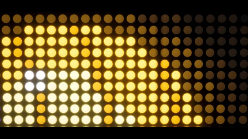 Use case
Make a realistic LED screen in Unity
An emissive texture with a dot mask stops looking like an LED wall once the camera moves. LED Studio models pitch, emitters and cabinets first, then its LED Board shader presents them from close-ups to the far end of a venue.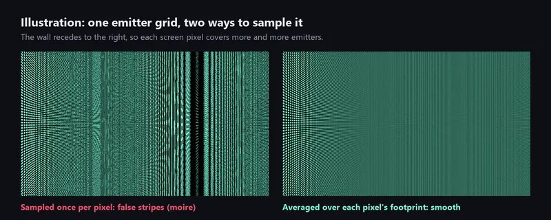 Article
Moire on LED screens in Unity, and how to fix it
Moire is aliasing between a screen's emitter grid and the camera's pixel grid. Why it grows with distance and motion, the usual shader and camera fixes, and how LED Studio blends emitters into a smooth image without changing brightness. Article