Moire on LED screens in Unity, and how to fix it
Why LED walls and monitor screens shimmer with moire in Unity, the standard fixes from mipmaps to TAA, and how LED Studio averages emitters by their size on screen.
Build an LED wall or a monitor in Unity and the close-up usually looks right: round dots, dark gaps, bright colors. Pull the camera back or pan across the screen, and bands start to ripple over the image, crawling and flickering with every camera move. That is moire, and it is a long-standing problem for screen shaders. A Unity Discussions thread from 2015 describes it exactly: an LED panel shader that looks fine up close, shows a moire pattern farther away and turns into a mess at long range.
This article explains where the pattern comes from, the standard fixes and their tradeoffs, and how LED Studio deals with it.
What moire is
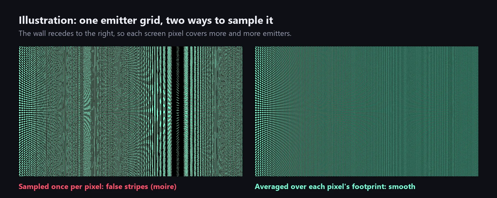
An LED screen is a regular grid of emitters. The camera samples the scene with a second regular grid: the pixels of the render target. While every emitter covers many pixels, the dots render cleanly. As the two grids approach the same size, each pixel lands on a slightly different part of its emitter, a little more on the bright dot here, a little more on the dark gap there. Those offsets add up to a slow beat across the screen: stripes, rings or checkerboards that are not in the content at all. Signal processing calls this aliasing; on screens it is called moire.
The cover illustration shows both cases: sampled once per pixel, a receding emitter grid breaks into false stripes; averaged over each pixel’s footprint, it fades into an even tone.
A round dot surrounded by a dark gap has much finer detail than its pitch suggests, so even emitters a few pixels wide can beat against the pixel grid. Once an emitter is smaller than a pixel, it cannot be drawn individually at all. The only correct result is the average color of the emitters the pixel covers.
Why it gets worse with distance and motion
Three things shrink emitters on screen:
- Distance. With a 60-degree vertical field of view at 1080p, an object one meter tall seen from one meter away spans about 935 pixels, so a 10 mm emitter seen from 10 m covers less than one pixel. The article on pixel pitch for game developers works through more cases.
- Angle. A board seen at a grazing angle, like a perimeter board along a pitch, compresses the grid in one direction. It can alias horizontally while it still looks clean vertically.
- Resolution and lens. Lower render resolutions and wider fields of view make every emitter smaller in pixels; a telephoto lens makes it larger.
Motion makes all of this visible. The beat depends on where emitters fall relative to pixel centers, so the smallest camera movement shifts it. A static moire can pass as texture; a moving one crawls and flickers, and the eye locks onto it. Contrast adds to it: small bright dots with wide dark gaps make the grid pattern stronger than wide emitters with narrow gaps.
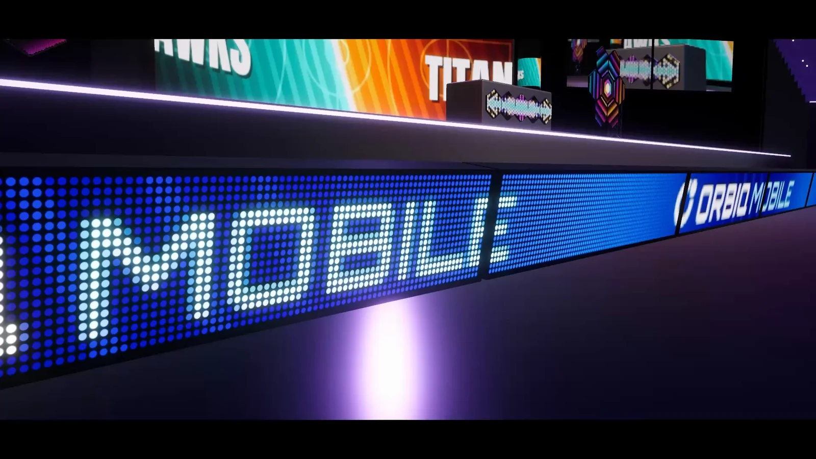 Perimeter boards in the arena film: on the nearest board the MOBILE lettering resolves into round emitters, while the farther boards read as smooth ORBIO MOBILE lettering.
The standard fixes
Every robust fix follows one rule: once the pixel grid can no longer resolve the emitter pattern, show the pattern’s average instead of point samples of it. These are the usual ways to get there:
- Mipmapped masks. When the dot shape comes from a mipmapped texture, the GPU picks smaller, pre-averaged levels as the pattern shrinks, based on the screen-space derivatives of the UVs. Dots computed procedurally from the UVs, as in the forum thread, get no mipmapping at all, which is why they alias so badly.
- Anisotropic filtering. Mip selection alone either blurs or aliases boards seen at grazing angles. Anisotropic filtering samples more along the compressed direction and keeps such textures clearer at shallow angles.
- Derivative-based anti-aliasing. Shader functions such as
fwidth,ddxandddytell a pixel shader how many emitters one pixel spans. Use that width to soften dot edges, and fade the dot pattern toward its average color as emitters approach pixel size. A reply in the thread suggests the same idea: when an LED gets smaller than a pixel, make it larger and dimmer. - Supersampling. Evaluate the dot mask at several positions inside each pixel and average them. It works at any angle but multiplies the cost of the mask.
- Temporal anti-aliasing. URP’s TAA smooths over several frames from a history buffer, which also calms leftover shimmer, at the risk of ghosting in fast motion. MSAA does not help here, because it smooths geometry edges while the dot pattern lives inside one quad.
- Distance fade. Blend from the dot pattern to the plain image by camera distance. It is easy to tune for one camera, but distance ignores field of view and resolution, so a zoomed shot either loses its detail or starts to shimmer. Derivatives measure what actually matters: emitter size in pixels.
- No pure point sampling. Point sampling content is fine when one texel maps to one emitter. Point sampling the dot pattern into screen pixels from far away is the moire generator itself.
How LED Studio handles it
LED Studio builds this behavior into its LED Board shader, so a board needs no custom fix:
- Close-Up Distance and Far Blend Distance. Every board, or the board profile it uses, has two distances. Below Close-Up Distance the shader emphasizes individual diode shape and glow; beyond Far Blend Distance the board blends toward smoother output for distant viewing.
- A reference camera plus real emitter size. Both distances are calibrated to a reference camera with a 60-degree vertical field of view at 1080p, and the shader also follows emitter screen size. A telephoto shot or a higher render resolution keeps emitter detail farther away, a wide shot averages sooner. That is the derivative approach, not a plain distance fade.
- The same average brightness at every distance. Near, far and subpixel output preserve the same average emitter brightness. Diffusion spreads each diode’s light around it, and distant content is averaged to reduce aliasing, so a board neither brightens nor darkens while it blends.
- Content reduction. Moire has a second source: content larger than the emitter grid. When a 1080p video lands on a 192 x 108 board, each emitter stands for many source pixels. Reduction modes decide how they are combined: Nearest, Box, Luma Priority, Edge Preserving Sharpen, Ordered Dither and Alpha Priority. The manual recommends Box for video and render textures, Edge Preserving Sharpen for images and Alpha Priority for opaque text, and Crisp text rasterization maps text pixels to whole LEDs.
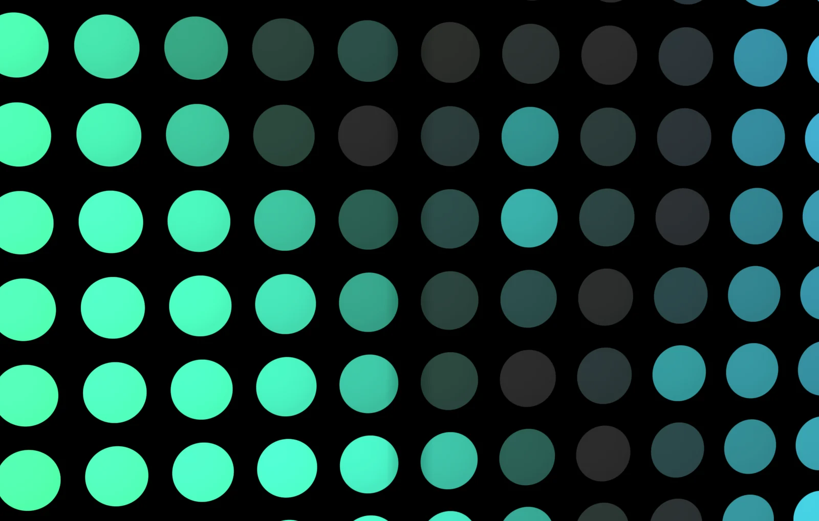 Up close, each emitter shows its round shape and brightness falloff, with black gaps between neighbors and some emitters dark.
The LED display basics page of the manual covers these settings, and the comparison with building an LED shader yourself lists what else a believable board needs beyond anti-aliasing.
What to tune
- Far Blend Distance. Lower it when a distant board still looks busy, raise it when boards lose their LED character too early in wide shots.
- Close-Up Distance. Set it to where the camera really gets close. For boards that never come near the camera, the performance guidance recommends disabling close-up mode.
- Fill ratio. It is the share of each pitch cell the emitter occupies, and lower values leave larger dark gaps. Wide gaps look striking up close and give the grid more contrast at mid distance.
- Pitch and emitter count. A coarser pitch makes emitters larger on screen, so the LED structure survives to longer distances. A finer pitch reads as a continuous image sooner.
- Reduction mode. Match it to the content, as above.
- Cabinet grid. Choose cabinet columns and rows that divide evenly into the logical resolution to avoid unnecessary seam artifacts.
- Camera. Test at the resolutions you ship, and use TAA in URP if other geometry still shimmers.
From LED Studio 1.7.0, changing viewing distances at runtime applies without restarting the content, so a cutscene can call SetViewingDistances per shot.
When moire is the look you want
Moire is also a visual cue. When a real camera films a screen, its sensor grid beats against the display grid, so stripes read as “this was filmed”: found footage, a news camera pointed at a monitor, a security feed. Some screen shaders add the pattern on purpose for that reason.
Treat it as an effect on top, not as the default state of every board. LED Studio aims for a stable image at every distance, so a deliberate filmed-screen look belongs in post-processing or in the footage itself, where you control its strength per shot.
Frequently asked questions
What causes moire on LED screens in Unity?
The emitter grid of the screen interferes with the pixel grid of the camera. When emitters shrink to a few pixels or less on screen, sampling the dot pattern once per pixel produces false stripes and rings that move with the camera.
Does TAA fix moire on an LED shader?
Only partly. Temporal anti-aliasing accumulates several frames and calms leftover shimmer, but it can ghost in fast motion and cannot recover a pattern that was sampled too coarsely. The real fix is to average the emitter pattern in the shader once emitters get small on screen.
How does LED Studio avoid moire?
Its LED Board shader blends emitters toward a smooth image as they shrink, using Close-Up and Far Blend distances calibrated to a 60-degree vertical field of view at 1080p and the actual emitter size on screen. Near, far and subpixel output keep the same average brightness, so nothing pops while it blends.
Why does my screen shader only shimmer while the camera moves?
The moire pattern depends on exactly where emitters fall relative to pixel centers. A still camera freezes it into a faint texture, while any movement shifts it every frame, and the eye notices moving stripes immediately.
LED screens, walls and signs that look like real hardware.
Keep reading
 Use case
Make a realistic LED screen in Unity
An emissive texture with a dot mask stops looking like an LED wall once the camera moves. LED Studio models pitch, emitters and cabinets first, then its LED Board shader presents them from close-ups to the far end of a venue.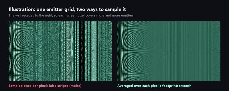 Comparison
LED Studio vs building an LED screen yourself
Unity has no LED display feature, only building blocks. A hand-built shader is fine for one flat screen; moire, text, curved shapes, live data and many panels are where LED Studio saves the work. Article