LED Display Basics
A real LED display is made from many small light sources arranged in a grid. Each light source is usually called an LED, diode, emitter, or pixel. LED Studio uses the word emitter because the package is simulating the visible light point, not just storing an image pixel.
Starting from the physical model matters: pitch, emitters, cabinets, seams, viewing distance, and brightness determine whether a display feels like installed hardware instead of a flat texture placed on a mesh.
Emitters, Pixels, and Logical Resolution
The logical resolution is the number of emitters the board contains, for example 192 by 108. This resolution is not the same thing as the final screen resolution of your game view. LED Studio first composes all text, images, video, UI, scores, and timers into this emitter grid. The LED shader then presents the grid on a mesh so it looks like a physical LED surface.
Beginner term - If a board has a logical resolution of 512 by 16, it behaves like a long ribbon display with 512 emitters across and 16 emitters high. |
Pitch and Viewing Distance
Pitch is the physical distance between adjacent emitters, measured in millimeters. A P2.5 display has a 2.5 mm pitch, while a P10 display has a 10 mm pitch. Smaller pitch means more detail at close range. Larger pitch looks more visibly pixelated and is usually viewed from farther away.
Pitch | Typical feel | Good use |
P2.5 / P3.9 | Fine detail, readable closer to camera | Stage backdrops, trade show walls, hero screens |
P5 / P6 | Balanced detail and visible LED character | Scoreboards, venue screens, medium-distance signage |
P10 / P16 / P20 | Chunky, obvious diode pattern | Large outdoor boards, stylized retro displays, distant ribbons |
Cabinets, Seams, and Bezels
Large LED walls are normally assembled from rectangular cabinet modules. The small gaps between cabinets create seams, and the dark structure around each module creates a bezel effect. LED Studio can draw these seams from the cabinet grid settings. For clean results, choose cabinet columns and rows that divide evenly into the logical resolution.
Brightness, Bloom, and Close-Up Detail
Real LED displays are bright light sources. In Unity, that usually means using HDR brightness and bloom in the camera or render pipeline. LED Studio also simulates emitter fill ratio, falloff, brightness response, and optional close-up diode lens detail. At far distances, the board can blend toward a smoother image to reduce distracting aliasing and moire artifacts.
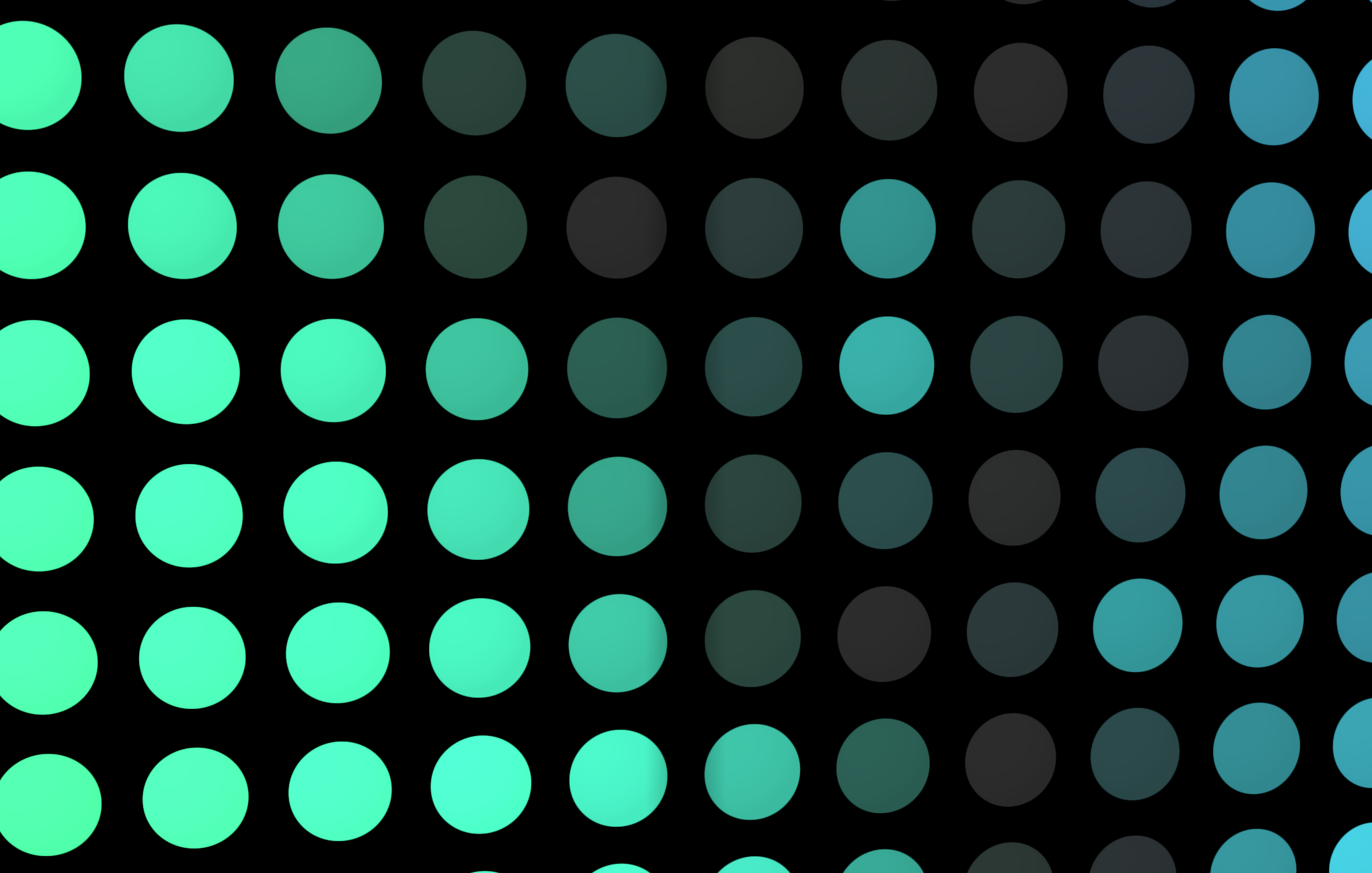
Emitter close-up: visible diode pitch, fill, and brightness falloff.
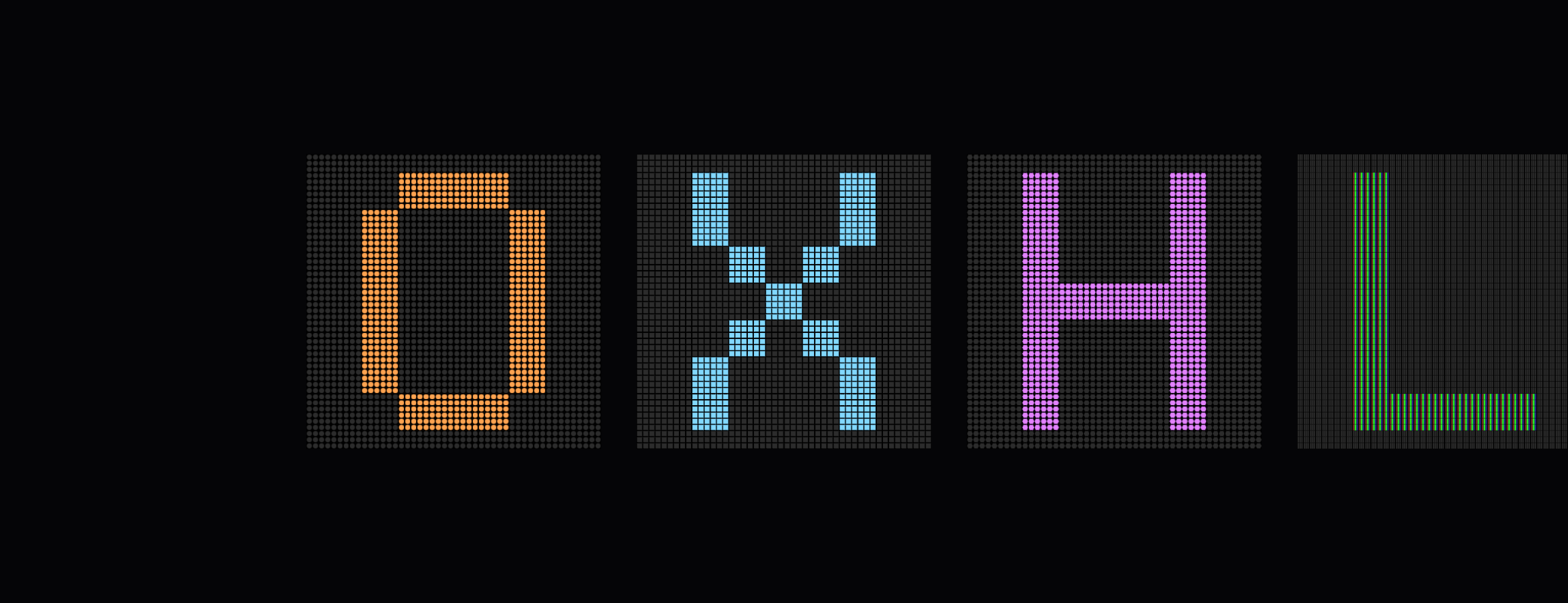
Emitter shape library: circle, block, hex, LCD