Core Workflow
The Board Controller
LedBoardController is the main runtime component. It owns the logical board texture, resolves inline settings or profile assets, discovers data sources, composes content, updates defects, binds material properties, participates in sync groups, and exposes the ILedBoardRuntime API for game code.
Inline Settings Versus Profiles
For one-off boards, inline settings on LedBoardController are enough. For repeated displays, create reusable assets from the Create > LED Studio menu, including Board Profiles, Topology assets, Source Assets, LED Compositions, Playlist Assets, Defect Profiles, and Quality Profiles. When a profile is assigned, the matching inline controller settings are ignored, including topology and generated housing.
Inline settings keep a single display quick to create, while reusable profiles keep larger productions consistent. The same approachable workflow can therefore scale from one sign to repeated panels and synchronized venue systems.
Asset | Purpose |
Board Profile | Logical resolution, pitch, topology, rear-body extrusion, front-frame settings, cabinet grid, emitter settings, and default reduction. |
Topology | Reusable generated board shape settings for flat and hexagonal panels, curved and corner wraps, 360-degree cylinders, pipe wraps, and LED spheres. |
Source Asset | Reusable text, image, timer, score, render texture, or UI Toolkit content. |
LED Composition | Reusable layered content with Source Asset layers, live input layers, zones, fit modes, priority, opacity, and optional reduction overrides. |
Playlist Asset | Timed sequence of direct Source Asset entries or reusable LED Composition entries with loop, sync group, transitions, and durations. |
Defect Profile | Procedural or mask-driven hardware wear and failure simulation. |
Quality Profile | Update budget, target update rate, reduction override, bloom, close-up mode, and defect quality. |
Topology
A board can be flat, hexagonal, curved, wrapped around a corner, closed into a 360-degree cylinder, or shaped into an LED sphere. The Board Wizard includes starting points for flat panels, ribbons, video walls, corner wraps, Cylinder 360, Pipe Wrap, Sphere, and Hex Panel Wall installations. Topology changes the generated physical surface while content continues to use a rectangular logical emitter grid.
Choose the Shape in the board's inline topology settings or in a reusable Topology asset. Sweep Angle, Radius, Face Side, Mesh Segments, and Physical Segments appear where the selected shape uses them. Mesh Segments controls geometric smoothness; Physical Segments describes the physical display sections. Sphere shapes also expose Bottom Latitude and Top Latitude, and curved or corner shapes expose Bend Direction.
Pipe Wraps and Vertical Bends
Horizontal bends wrap a board from left to right around a vertical column. Vertical bends wrap it from top to bottom around a horizontal pipe, rail, or arm. Set Bend Direction on Curved or Corner shapes; a 360-degree curved sweep closes the wrap. The Pipe Wrap wizard preset starts with a vertical cylindrical display.
To roll text around the vertical circumference, set the Text Source's Scroll Axis to Vertical and enable Seamless Wrap. Bend Direction controls the board's geometry, while Scroll Axis controls how its content moves.
LED Spheres
Sphere topology uses an equirectangular layout, with longitude across the content width and latitude across its height. Sweep Angle chooses the longitude coverage; 360 degrees closes the surface around the sphere. Bottom Latitude and Top Latitude choose the vertical coverage. The default range is -70 to 70 degrees, leaving openings above and below the display.
Set Bottom Latitude to -90 to close the bottom pole, Top Latitude to 90 to close the top pole, or both for a complete sphere. Closed poles have no rim frame or body side. Face Side selects an outside or inside display. Radius is a minimum: the sphere can grow to accommodate the chosen emitter count and pitch. Keep important text away from the poles, where the surface narrows.
Hexagonal Boards
Hexagon Pointy Top and Hexagon Flat Top create flat, six-sided boards with matching rear-body and front-frame housing. Emitters outside the slanted outline are hidden. Follow the inspector's emitter-resolution hint when the outline should be a regular hexagon; an unsuitable width-to-height ratio stretches it.
The Hex Panel Wall wizard preset creates seven separate hexagonal boards in a honeycomb, using a Spatial group to share one canvas across the physical gaps. Use a hexagonal Cabinet Layout when the honeycomb should be a panel pattern within one board instead.
Rear Body
Topology and housing changes rebuild the generated LED meshes while sliders, numeric fields, toggles, and dropdowns are adjusted, so curved, framed, and extruded boards stay visually current during authoring.
Rear Body adds physical cabinet depth behind the LED face. Enable it on a board controller or board profile, set Body Depth in meters, and optionally assign a default housing material or per-side overrides for the left, right, top, bottom, and back. The front submesh remains the LED display. Closed curved boards omit caps at their joined ends. Spheres generate housing along open boundaries, and closed poles have no body side.
Adding rear depth and housing materials lets the display occupy the scene as a believable object from more than the front camera angle, which is especially valuable for corners, suspended boards, ribbons, and close venue shots.
Front Frame
Front Frame adds generated geometry outside the LED surface and in front of its unchanged screen plane, making the display appear recessed. It is independent of Rear Body: use the frame by itself as a closed lip for a wall-integrated panel, or enable both controls for a complete cabinet. The LED surface vertices, UVs, physical size, origin, and interaction plane stay unchanged.
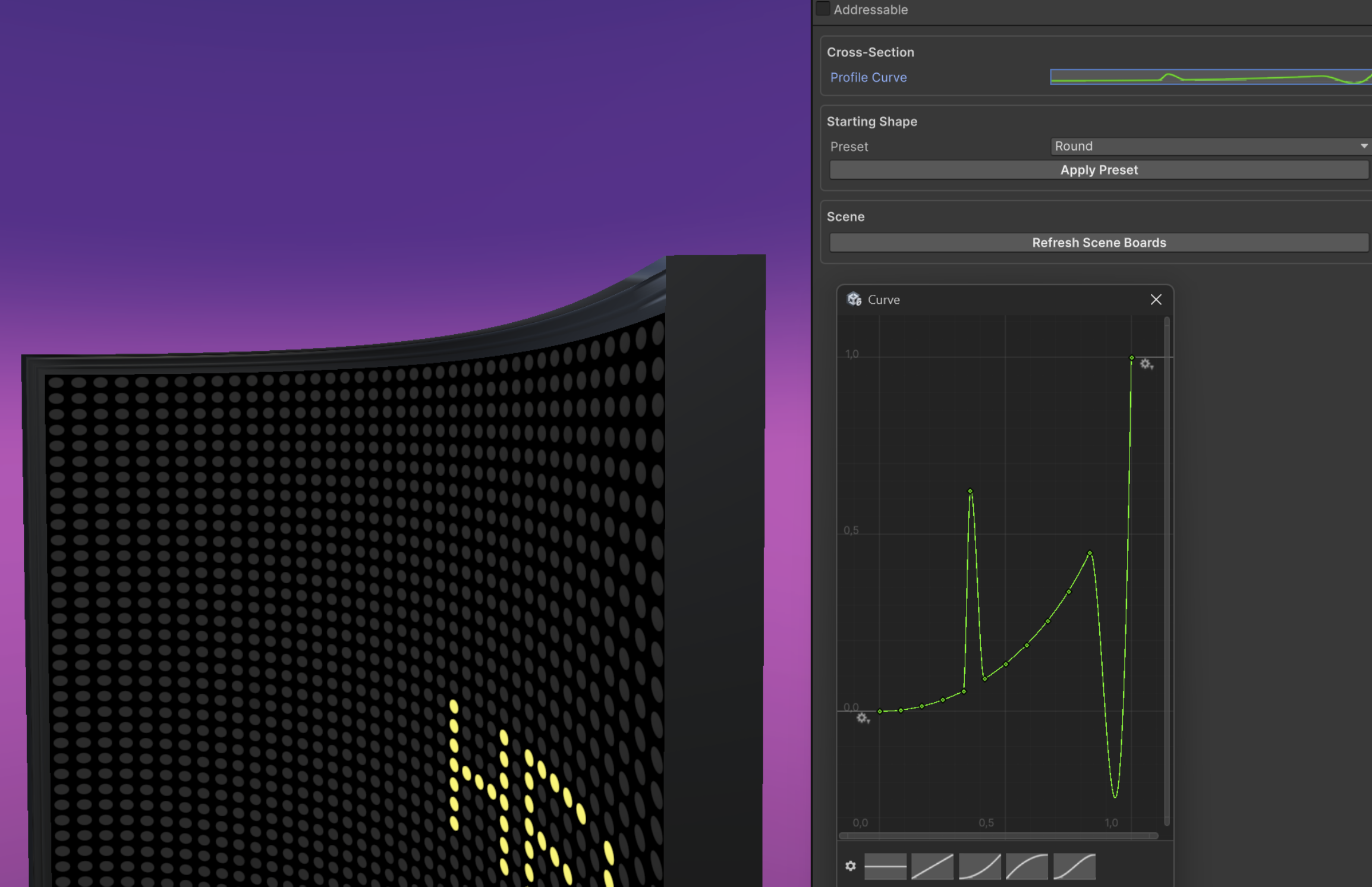
Frames follow flat, hexagonal, corner, curved, and spherical board outlines. Closed 360-degree surfaces have no frame across the joined seam. On spheres, frame rims follow open boundaries; closed poles have no rim.
Style | Shape and typical use |
|---|---|
None | Disables the front frame and preserves the original generated board appearance. |
Chamfer | A single straight slope for crisp industrial bezels and low-detail venue hardware. |
Round | A convex quarter-round profile for soft display surrounds and product close-ups. |
Cove | A concave transition that suits screens recessed into walls or scenic panels. |
Ogee | An S-curve profile for decorative signs and architectural installations. |
Stepped | A two-stage profile for layered, technical, or gallery-style surrounds. |
Custom | A reusable LedBoardFrameProfile curve for branded or project-specific molding. |
The housing controls are intentionally expressed in small physical values:
- Frame Width: grows the frame outward from every LED-surface edge. Its slider covers 0.001 to 0.1 m; 0.025 m (25 mm) is the starting value.
- Screen Recess: controls how far the frame rises in front of the LED plane. Its slider covers 0.001 to 0.1 m; 0.01 m (10 mm) is the starting value.
- Profile Detail: controls subdivisions across rounded, cove, ogee, stepped, and custom cross-sections from 1 to 32. Chamfer uses one segment. Start at 6 and increase only when a close camera reveals faceting.
- Custom Profile: appears when Front Frame is Custom. Create or assign a reusable LedBoardFrameProfile, then edit its normalized curve. Horizontal position is outward distance and vertical value is forward rise, both from 0 to 1. Seed Chamfer, Round, Cove, Ogee, or Stepped before refining the curve. Loaded scene boards update automatically. If no custom profile is assigned, Round is used as a safe fallback.
- Front Frame Material: assigns a dedicated finish in Housing Material Overrides. When empty, the default housing material and built-in side-material fallback are used.
Example Starting Points
Use Cove at 0.025 m width and 0.01 m recess with Rear Body off for a wall-integrated lip. Use Chamfer at 0.015 m width and 0.006 m recess with a 0.05 m Rear Body for a touring cabinet. For a hero close-up, try Round or Ogee at 0.03 m width, 0.012 m recess, and Profile Detail 12. For branded molding, use Custom at 0.035 m width, 0.015 m recess, and Profile Detail 12 to 16, then seed Ogee or Stepped before refining the curve.